Product Documentation
Guides and examples for CubeLab hardware, the browser simulation, and the secure console environment.
CubeLab
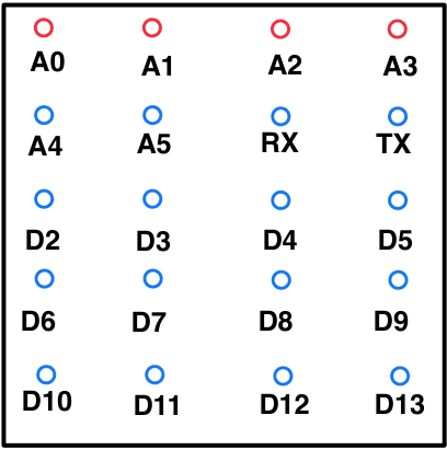
The CubeLab is a 4×4×4 LED matrix controlled by a microcontroller. It’s typically powered by a single-cell 3.7 V battery (with a regulated 5 V rail for logic, if required) and consists of 64 LEDs arranged in 4 layers of 16 columns.
- Layers (example): [A0, A1, A2, A3]
- Columns (example): [A4, A5, RX(D0), TX(D1), D2, D3, D4, D5, D6, D7, D8, D9, D10, D11, D12, D13]
Diagram of CubeLab wiring & connections:
Steps to Operate the CubeLab
- Install the Arduino IDE. Download it from the official site and follow the guide for your OS.
- Set up the CubeLab.
- Kit: Watch the assembly video; ensure all connections match your pin map.
- Finished unit: Proceed to connect to your microcontroller/USB and verify power.
- Write code. Open the Arduino IDE and create your sketch. See examples below.
- Upload code. Select the correct board & port, then upload.
- Power the CubeLab. Use a charged 3.7 V battery (with proper regulation for your board as needed).
Examples (Arduino / C++)
Tip: use arrays for pin maps rather than numeric ranges so you don’t depend on implicit numbering of A/D pins.
// Adjust pins to your board:
// Note TX is D1; if you include TX, don't duplicate D1 again.
const int layers[4]  = {A0, A1, A2, A3};
const int columns[16]= {A4, A5, 0, 1, 2, 3, 4, 5, 6, 7, 8, 9, 10, 11, 12, 13};

void setup() {
  for (int i = 0; i < 4;  i++) pinMode(layers[i], OUTPUT);
  for (int i = 0; i < 16; i++) pinMode(columns[i], OUTPUT);
  // Default OFF: columns LOW? depends on your wiring (common anode/cathode).
  // Set a known state here:
  for (int i = 0; i < 16; i++) digitalWrite(columns[i], LOW);
  for (int i = 0; i < 4;  i++) digitalWrite(layers[i], HIGH); // e.g., HIGH = layer off
}// Example assumes: column HIGH turns LED on, layer LOW selects layer (inverted).
void loop() {
int col = columns[0]; // pick a column
int lay = layers[0]; // pick a layer
digitalWrite(col, HIGH); // turn on column
digitalWrite(lay, LOW); // enable layer
delay(500);
// clear
digitalWrite(col, LOW);
digitalWrite(lay, HIGH);
delay(500);
}void loop() {
int col = columns[1];
int lay = layers[0];
// on
digitalWrite(col, HIGH);
digitalWrite(lay, LOW);
delay(500);
// off
digitalWrite(col, LOW);
digitalWrite(lay, HIGH);
delay(500);
}void loop() {
int lay = layers[0];
// turn all columns on
for (int i = 0; i < 16; i++) digitalWrite(columns[i], HIGH);
digitalWrite(lay, LOW);
delay(600);
// clear
for (int i = 0; i < 16; i++) digitalWrite(columns[i], LOW);
digitalWrite(lay, HIGH);
delay(400);
}void loop() {
for (int l = 0; l < 4; l++) {
// Turn on some pattern (here: all columns)
for (int i = 0; i < 16; i++) digitalWrite(columns[i], HIGH);
digitalWrite(layers[l], LOW); // enable layer
delay(3); // small persistence
digitalWrite(layers[l], HIGH); // disable
// Clear columns if needed for next step
for (int i = 0; i < 16; i++) digitalWrite(columns[i], LOW);
}
}void loop() {
// naive demo; adapt to your physical mapping (x,y,z -> index in columns[] & layers[])
for (int i = 0; i < 4; i++) {
int col = columns[i]; // diagonal "column"
int lay = layers[i];
digitalWrite(col, HIGH);
digitalWrite(lay, LOW);
delay(200);
digitalWrite(col, LOW);
digitalWrite(lay, HIGH);
}
}Simulation
LED Cube Simulation
Design and test Arduino-style sketches for a 4×4×4 LED cube directly in the browser. Pick a product (pin map), choose a color with the picker, paste a sketch, and run it live on the 3D cube.
loop() on the next yield.Sketch API (C++ like)
void setup()— runs once.void loop()— repeats until you press Stop.pinMode(PIN, MODE)— accepted (no-op in sim, for compatibility).digitalWrite(PIN, HIGH|LOW)— toggles a layer pin (e.g.A0..A3) or a column pin (depends on product pin map).delay(ms)— pauses; cancellable by Stop.- Helpers:
layerOn/Off(y),columnOn/Off(x,z),ledOn/Off(x,y,z),setColor("#hex")(optional; the color picker also sets LED color).
Coordinates are 0…3. Columns are addressed by (x,z), layers by y. The exact pin names for columns vary by product; see the Pin Map on the simulation page. Multiple statements on one line are supported (;), but one per line is clearer.
void setup() {
  // quick layer pulse
  digitalWrite(A0, HIGH);
  delay(200);
  digitalWrite(A0, LOW);
}

void loop() {
  // blink one voxel
  ledOn(1, 1, 1);
  delay(200);
  ledOff(1, 1, 1);
  delay(200);
}// Keep all layers on for a tall beam
void setup() {
layerOn(0);
layerOn(1);
layerOn(2);
layerOn(3);
}
void loop() {
// Perimeter spin (clockwise)
columnOn(0, 0); delay(90); columnOff(0, 0);
columnOn(1, 0); delay(90); columnOff(1, 0);
columnOn(2, 0); delay(90); columnOff(2, 0);
columnOn(3, 0); delay(90); columnOff(3, 0);
columnOn(3, 1); delay(90); columnOff(3, 1);
columnOn(3, 2); delay(90); columnOff(3, 2);
columnOn(3, 3); delay(90); columnOff(3, 3);
columnOn(2, 3); delay(90); columnOff(2, 3);
columnOn(1, 3); delay(90); columnOff(1, 3);
columnOn(0, 3); delay(90); columnOff(0, 3);
columnOn(0, 2); delay(90); columnOff(0, 2);
columnOn(0, 1); delay(90); columnOff(0, 1);
// Layer scan with all columns on
columnOn(0,0); columnOn(1,0); columnOn(2,0); columnOn(3,0);
columnOn(0,1); columnOn(1,1); columnOn(2,1); columnOn(3,1);
columnOn(0,2); columnOn(1,2); columnOn(2,2); columnOn(3,2);
columnOn(0,3); columnOn(1,3); columnOn(2,3); columnOn(3,3);
layerOn(0); delay(120); layerOff(0);
layerOn(1); delay(120); layerOff(1);
layerOn(2); delay(120); layerOff(2);
layerOn(3); delay(150); layerOff(3);
columnOff(0,0); columnOff(1,0); columnOff(2,0); columnOff(3,0);
columnOff(0,1); columnOff(1,1); columnOff(2,1); columnOff(3,1);
columnOff(0,2); columnOff(1,2); columnOff(2,2); columnOff(3,2);
columnOff(0,3); columnOff(1,3); columnOff(2,3); columnOff(3,3);
delay(120);
}void setup() {
layerOff(0); layerOff(1); layerOff(2); layerOff(3);
}
void loop() {
// Drop at (x=1,z=2)
columnOn(1,2); layerOn(3); delay(90); layerOff(3); columnOff(1,2);
columnOn(1,2); layerOn(2); delay(90); layerOff(2); columnOff(1,2);
columnOn(1,2); layerOn(1); delay(90); layerOff(1); columnOff(1,2);
columnOn(1,2); layerOn(0); delay(120); layerOff(0); columnOff(1,2);
// Drop at (x=2,z=1)
columnOn(2,1); layerOn(3); delay(90); layerOff(3); columnOff(2,1);
columnOn(2,1); layerOn(2); delay(90); layerOff(2); columnOff(2,1);
columnOn(2,1); layerOn(1); delay(90); layerOff(1); columnOff(2,1);
columnOn(2,1); layerOn(0); delay(120); layerOff(0); columnOff(2,1);
// Drop at (x=0,z=3)
columnOn(0,3); layerOn(3); delay(90); layerOff(3); columnOff(0,3);
columnOn(0,3); layerOn(2); delay(90); layerOff(2); columnOff(0,3);
columnOn(0,3); layerOn(1); delay(90); layerOff(1); columnOff(0,3);
columnOn(0,3); layerOn(0); delay(120); layerOff(0); columnOff(0,3);
delay(120);
}Secure Console, Kria KV260, and Runtime Monitor
Secure Console Environment
The Secure Console lets you open a temporary, authenticated web terminal to shared lab devices (Kria, Jetson, Coral) without exposing them to the public internet. Access is granted per user/per device—if you don't see a device, request access from your instructor or the project owner.
rm -rf, random reboot, flashing, repartitioning, etc.) unless you have explicit approval. Sessions may be logged.Access a shared board
- Request accessAsk your instructor / project owner to grant you access to a device (e.g. Kria KV260). Once approved, you'll see it on the Devices page and you'll be able to open its console.
- Open the Devices pageIn the Cube Laboratory site, go to
/devicesand select the Kria KV260 device card. - Launch the Secure ConsoleClick "Open web terminal". A new page opens with a full-screen terminal connected to the device.
- Log inUse the credentials provided by the owner. Credentials can change—always use the latest instructions from your instructor.
- Verify you are on the KriaQuick environment checksbash
uname -m
cat /etc/os-release
python3 --version
gcc --version
make --version
The Kria KV260 image used in this course is typically aarch64 and runs a PetaLinux build.
Runtime Monitor (RTM) with R2U2
The Runtime Monitor (RTM) checks a live data stream against safety/quality rules. On the Kria board we use R2U2 as the monitor engine. You feed it:
- a specification compiled into a binary (
.bin) that encodes the rules you want enforced, and - a trace (CSV) where each row is a new frame/step of sensor or model outputs (for example: contrast/blur/brightness for an eye image).
Kria RTM quickstart (example: eye image metrics)
This example treats each CSV row as: contrast,blur,brightness in the range 0–255.
cat > ~/eye_trace.csv <<'CSV'
120,10,140
118,12,142
115,18,145
110,25,150
100,35,155
90,45,160
80,55,165
95,40,170
110,20,175
130,12,180
CSVcat > ~/eye.map <<'MAP'
contrast:0
blur:1
brightness:2
MAPcat > ~/eye.c2po <<'C2PO'
INPUT
contrast, blur, brightness: int;
DEFINE
too_dark := (brightness < 60);
too_bright := (brightness > 200);
low_contrast := (contrast < 40);
too_blurry := (blur > 40);
FTSPEC
too_dark -> F[0,5] (!too_dark);
too_bright -> F[0,5] (!too_bright);
low_contrast -> F[0,8] (!low_contrast);
too_blurry -> F[0,6] (!too_blurry);
C2POcd ~/r2u2
python3 compiler/c2po.py -bz --output ~/eye_spec.bin --map ~/eye.map ~/eye.c2po
ls -lh ~/eye_spec.bin# Run by redirecting stdin:
~/r2u2_install/bin/r2u2 ~/eye_spec.bin < ~/eye_trace.csv
# Or pass the trace file as arg 2:
# ~/r2u2_install/bin/r2u2 ~/eye_spec.bin ~/eye_trace.csvOutput format is <formula_id>:<timestamp>,<T|F>. The formula IDs are assigned by the order of rules in FTSPEC.
Interpreting RTM output
- formula_id: which rule is being reported (0 = first rule in
FTSPEC, 1 = second, etc.). - timestamp: the trace row index (0-based). Row 0 is the first frame, row 1 the next frame, and so on.
- T / F: whether the rule is satisfied at that time.
~/r2u2_install/bin/r2u2 ~/eye_spec.bin < ~/eye_trace.csv | grep ',F$' || trueF[0,5]). The monitor may need to read enough future samples to decide whether a recovery happened inside the window. The timestamp in the output still indicates which frame the rule applies to.Where R2U2 is installed on the Kria
On the Kria board image used for this project, the R2U2 binary is placed here:
ls -lah ~/r2u2_install/bin/
~/r2u2_install/bin/r2u2 --help || true